-
Products
-
-
-
-
Component Parameter Tester
-
Semiconductor C-V Analyzer
-
Impedance Analyzer
-
Benchtop Type LCR Meter
-
Handheld LCR Meter
-
DC Bias Current Source
-
Automatic Transformer Test system
显示更多 -
-
Micro Signal Type Tester
-
Precision Source Measurement Unit
-
Low Noise Precision Power Supply
-
DC Resistance Meter
-
Insualtion Resisitance Meter
-
Battery Tester
-
Digit Multimeter
显示更多 -
-
Power Electronic Tester
显示更多 -
Electrical Safety Tester and Cable Tester
-
Multifunction Safety Compliance Analyzer
-
Impluse Winding Tester
-
Cable / Harness Meter
-
Hipot Tester
-
Ground Bond Tester
显示更多 -
-
Accessories
-

About Us
Updated Automatic Transformer Test System TH2840 Series
The industry’s fastest test speed, the industry’s highest test level, the industry’s highest bias voltage, and the industry’s most user-friendly experience.


Automatic Transformer Test System TH2840
The industry’s fastest test speed, the industry’s highest test level, the industry’s highest bias voltage, and the industry’s most user-friendly experience.
Introduction of Innovation
1 LCR test parameters changed from the original two parameters to 4 parameter displays; combined LCR measurement display and sorting display;
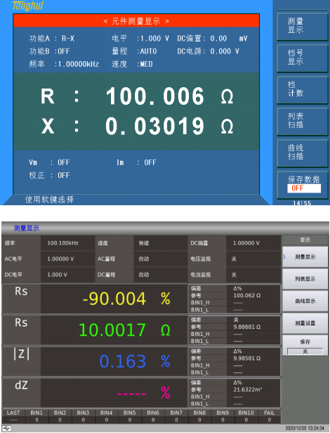
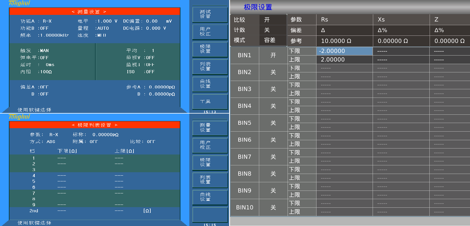
2 The LCR test incorporates the nominal value and reference value settings, making it easier for customers to understand and use. Cancel the auxiliary file and cancel the secondary parameter file
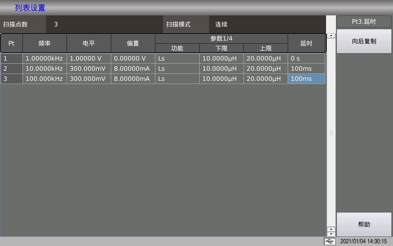
3 The frequency, level, offset, function, and delay of each point of the list scan can be set independently, which meets the needs of most customers.
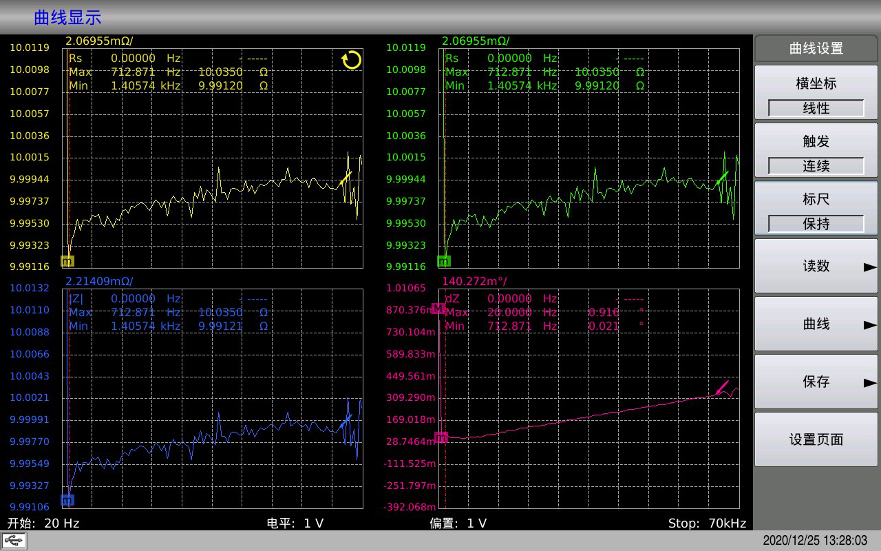
4 LCR curve scanning split-screen display.
5 Convenient operation and intuitive display
Handler setting interface
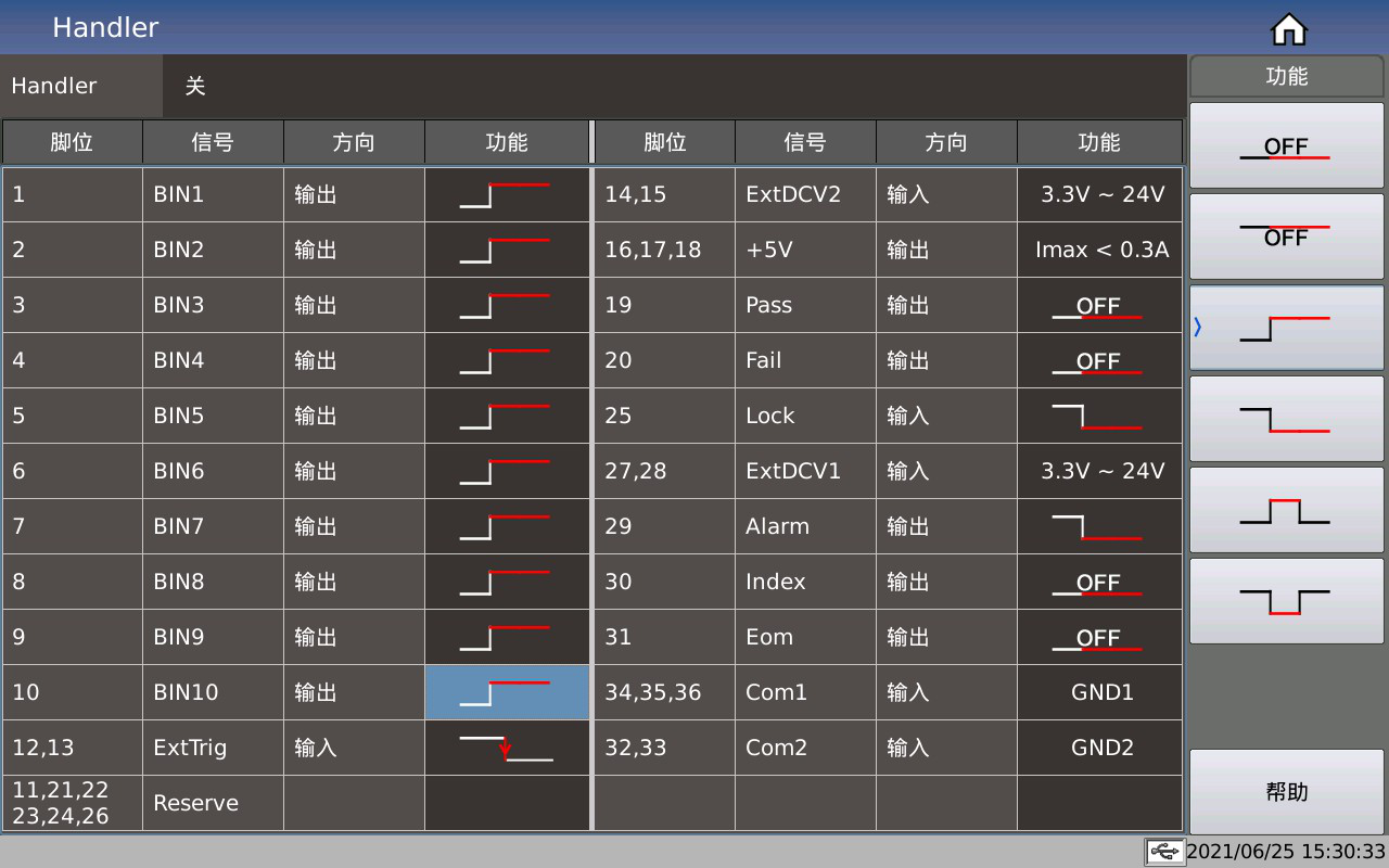
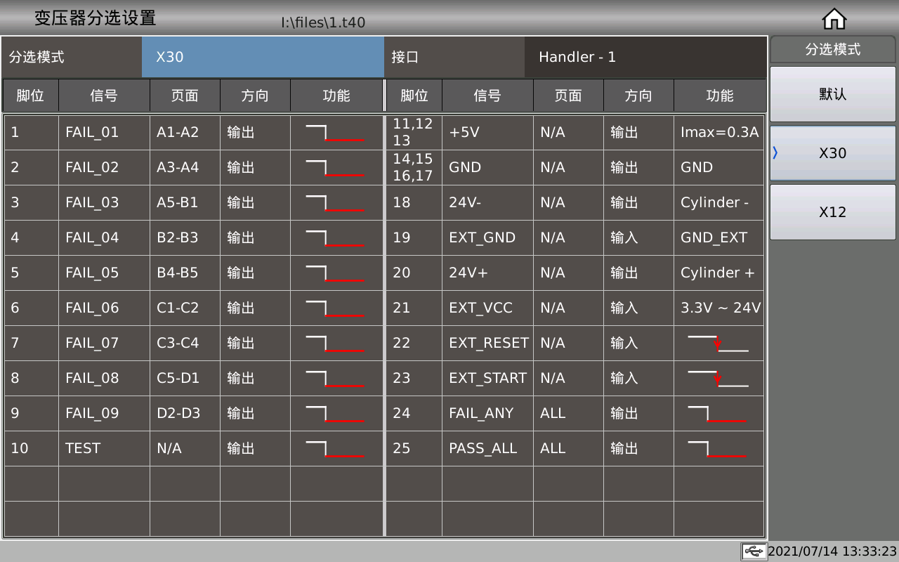
The Handler sorting mode setting of transformer scanning can give a maximum of 30 sorting signal outputs.
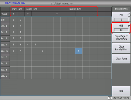
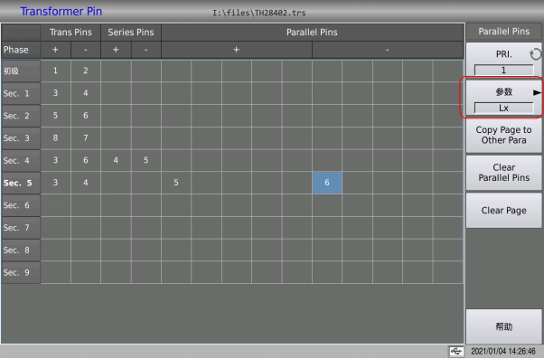
6 When setting pins in the past, when you need to connect pins in series and in parallel, you need to enter different sub-pages:

7 The setting of the test condition of the compressor is more concise and convenient. For the relevant parameters of Lx, you need to enter 6-7 different sub-pages:


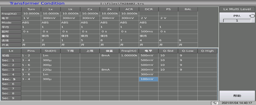
Now multiple parameters can be switched on one page, and all relevant parameters of Lx can be set in one table:
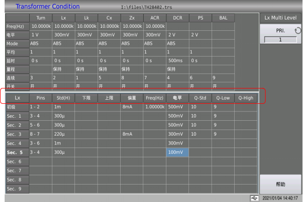
Cancel the range setting function used in the above picture, and change to the series-parallel equivalent mode of the picture in Article
8 Transformer scan: Each scan parameter can be averaged and delayed to increase stability without affecting the test speed of other parameters.
Both the positive and negative terminals of the PS can be input to 12 pins, and the background colour of the selected parameter will be different from other parameters8.
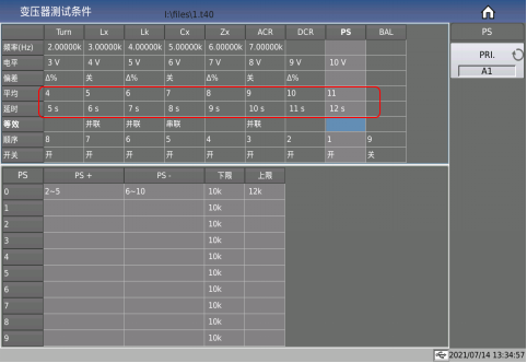
9 Transformer scanning: Multi-pin use 1-6, instead of 1, 2, 3, 4, 5, 6. Simplify the display page, improve the input efficiency.
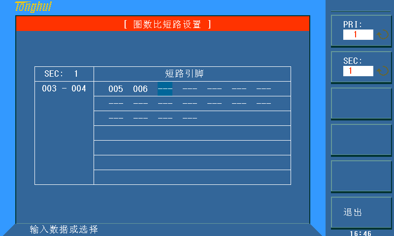
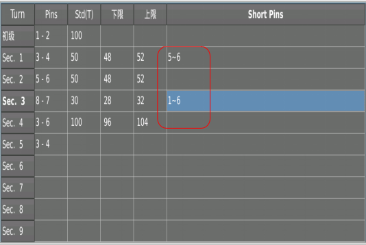
10 Transformer scan: Each parameter has its own independent series and parallel pin settings, which is more flexible.
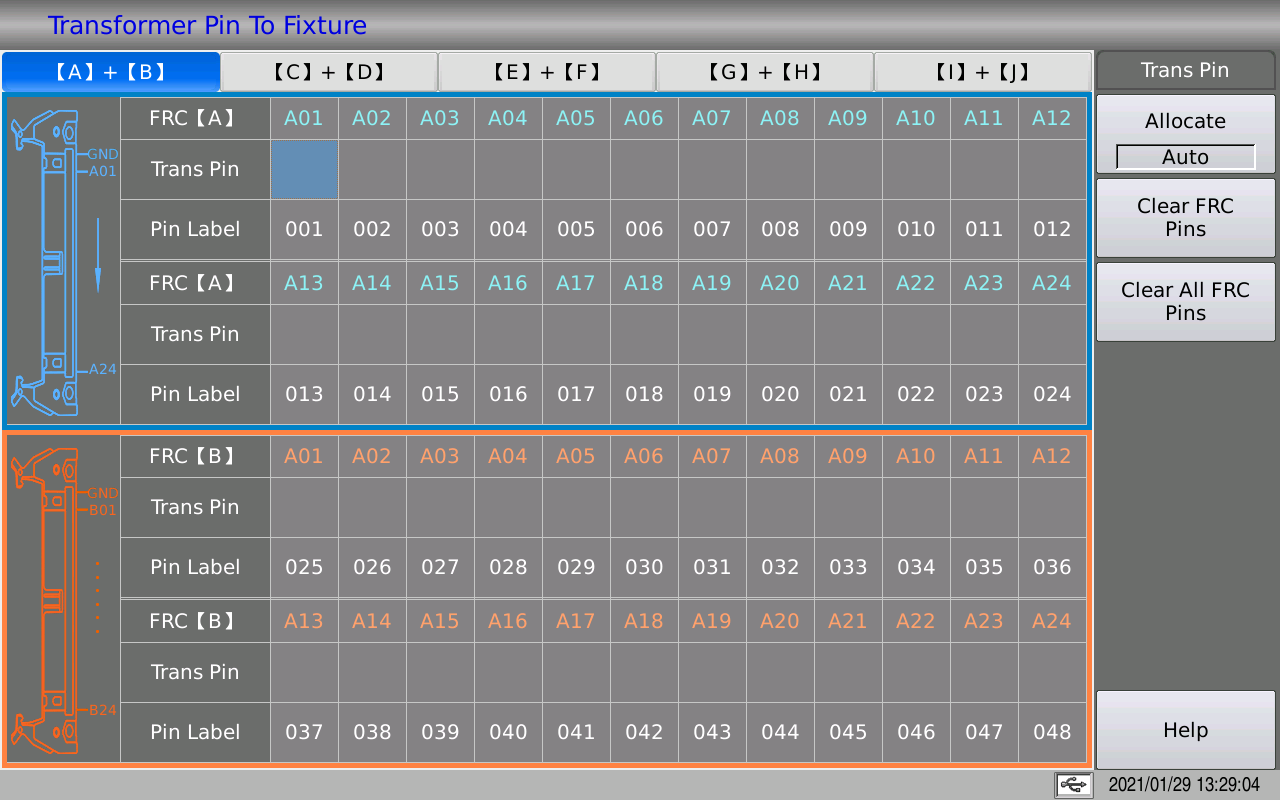
11 Pin related page
After a collective discussion by the software designers, the design goals were put forward, and with the assistance of Cui Xiang, the final results were quickly seen, which accelerated the design speed.
The interface adds elements such as pictures, colors, borders, and improves the correlation between the pin settings and the test horns. Users can see it at a glance, without too much explanation, and they will operate when they see the page.
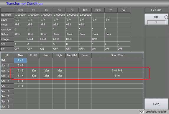
12 The Lk setting saves the input leakage inductance pin, directly input the nominal value at the corresponding pin, and the upper and lower limits are sufficient

13 The balance sweep is changed from 5 to 10 points, and the mode is changed to absolute value switch. According to this switch, whether the final result of the formula is positive and then compare
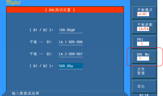
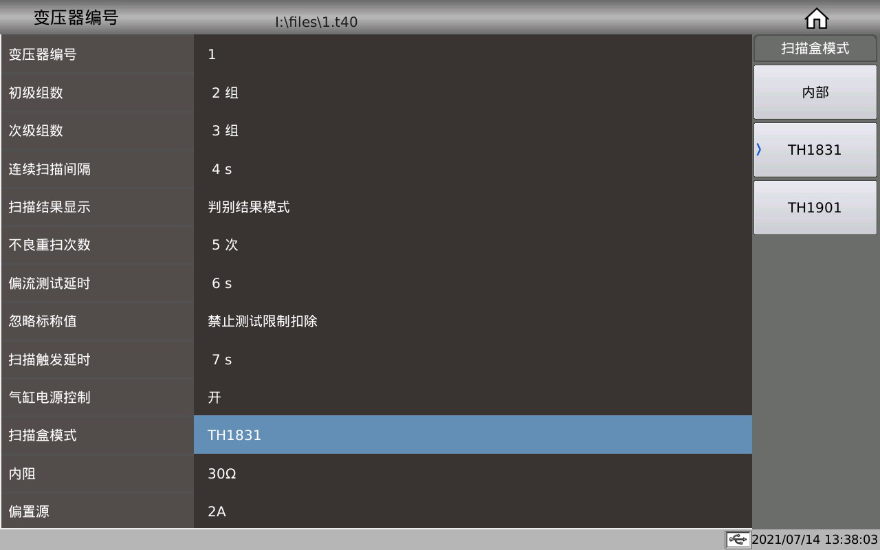
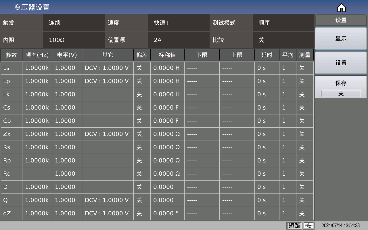
14. New functions in the transformer number interface A Scan box mode B Internal resistance C Bias source.
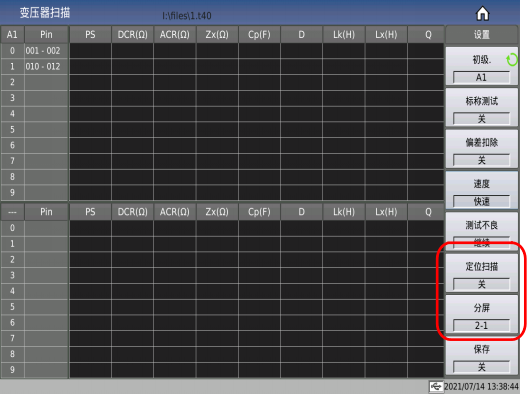
15 The transformer scan interface can directly use the positioning scan function and the split screen function.
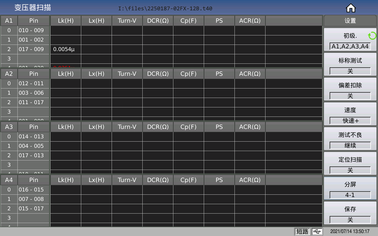
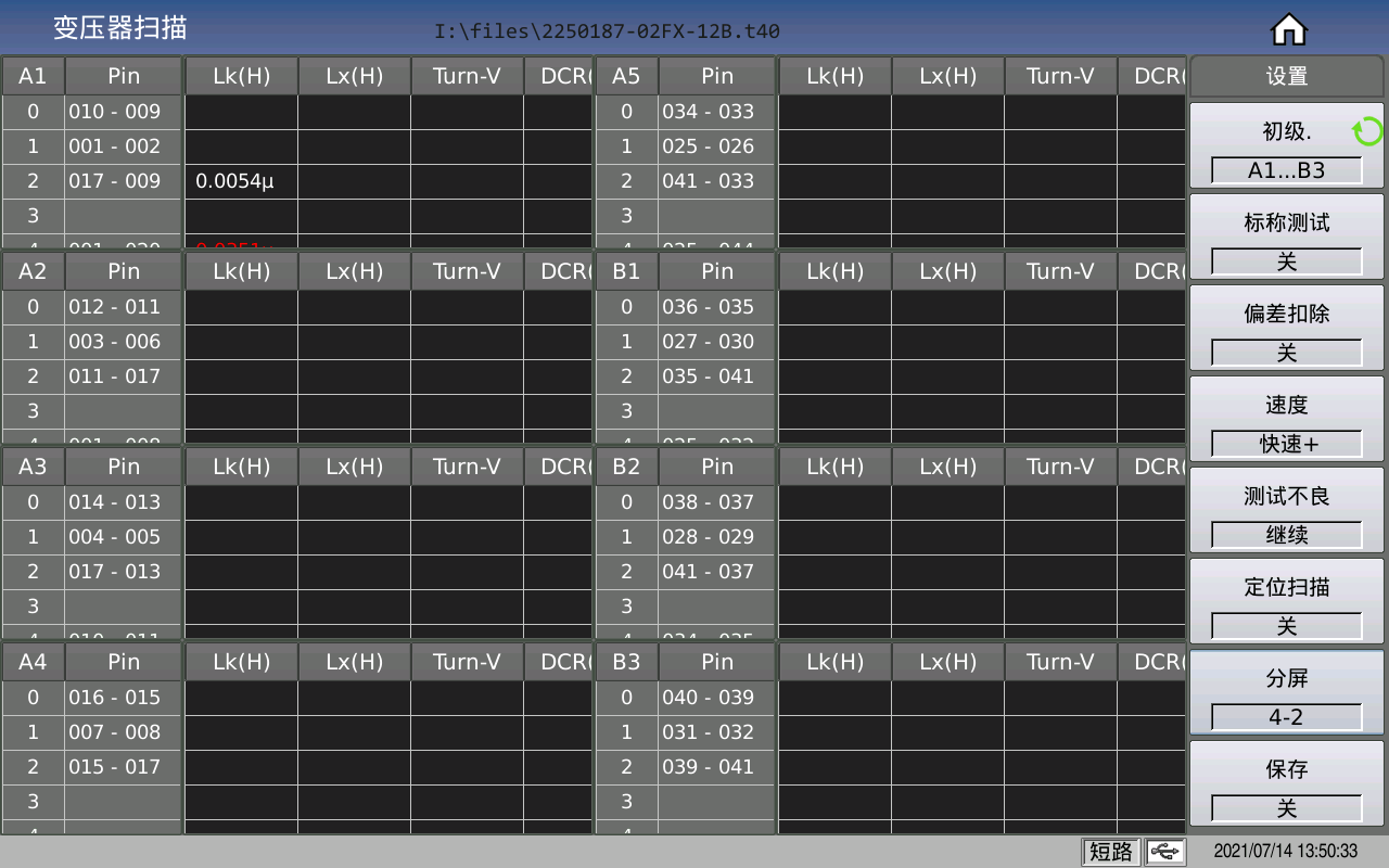
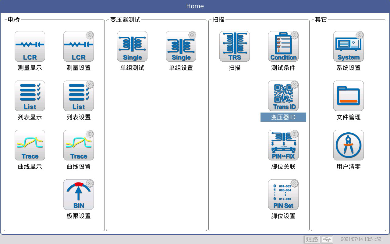
16 Press the home button to display all interface entries
17 Transformer single group test function.
COOKIES
Our website uses cookies and similar technologies to personalize the advertising shown to you and to help you get the best experience on our website. For more information, see our Privacy & Cookie Policy
COOKIES
Our website uses cookies and similar technologies to personalize the advertising shown to you and to help you get the best experience on our website. For more information, see our Privacy & Cookie Policy
These cookies are necessary for basic functions such as payment. Standard cookies cannot be turned off and do not store any of your information.
These cookies collect information, such as how many people are using our site or which pages are popular, to help us improve the customer experience. Turning these cookies off will mean we can't collect information to improve your experience.
These cookies enable the website to provide enhanced functionality and personalization. They may be set by us or by third-party providers whose services we have added to our pages. If you do not allow these cookies, some or all of these services may not function properly.
These cookies help us understand what you are interested in so that we can show you relevant advertising on other websites. Turning these cookies off will mean we are unable to show you any personalized advertising.


